Here it goes. Remove the original switch and replace it with a small SPST needed for calibration.
Next I remove the original ‘effect’ LED and tack it to the back of the board. It can be completely removed but I just left it there for testing purposes. Install a new LED/Holder.
Wire LED to its new power supply.
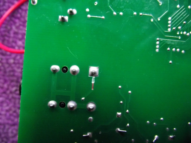
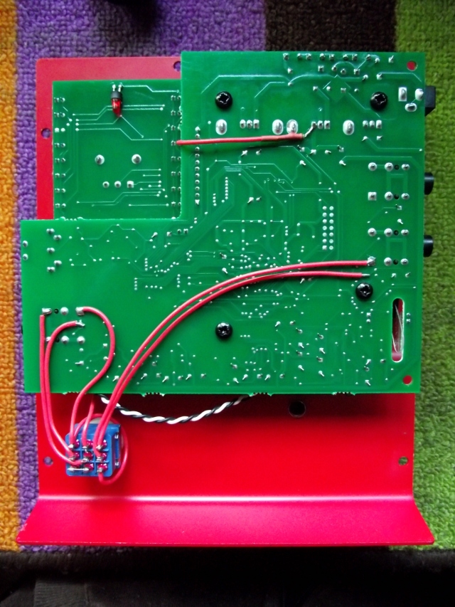
Next, cut a couple of traces, install a new switch and wire it for true-bypass.
The wires from the jacks to the 3PDT and from the 3PDT back to the board were later replaced with shielded wire as the wet signal was leaking into the dry signal when the pedal was bypassed. Remember to connect only one side of the shield on each wire.
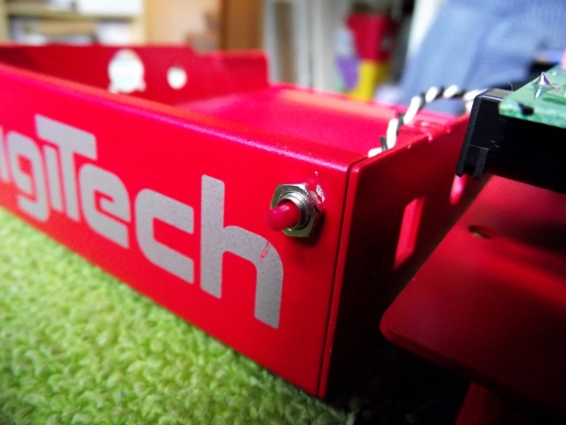
To finish it up, I drill the holes for the calibration switch and footswitch jack, install them and wire the footswitch jack. The footswitch is not ready yet because I forgot to order a few parts. I’ll take the chance to order a different color enclosure as I was going to use this butt-ugly red one I bought a long time ago. When that is done I’ll update this entry. (go HERE to see the finished switcher)
And finally just close it up and test it.
Done!

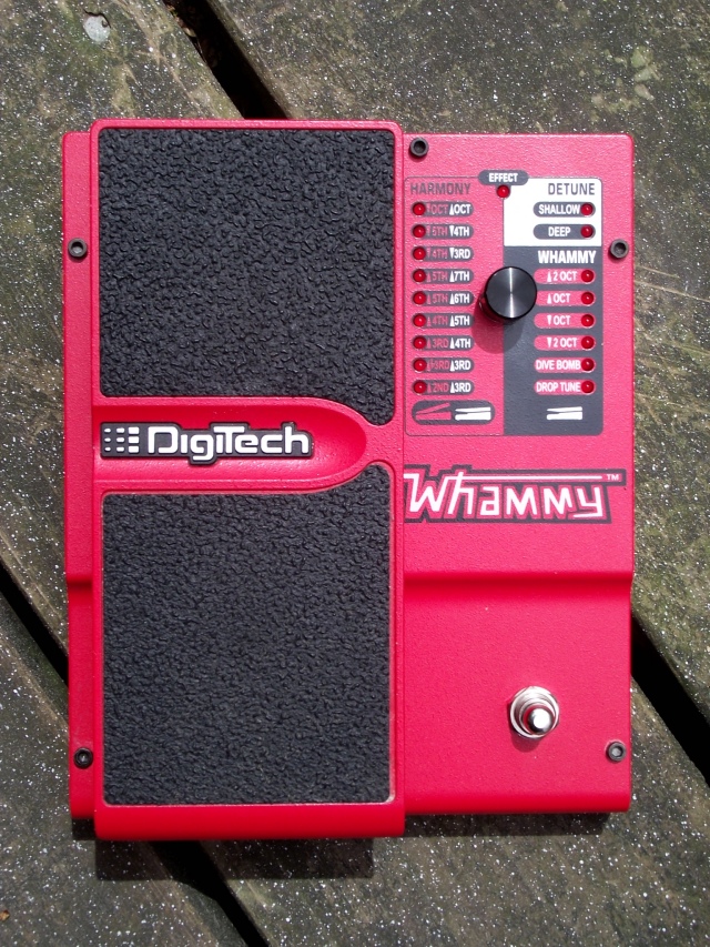
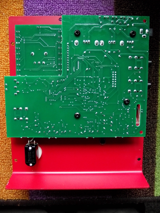
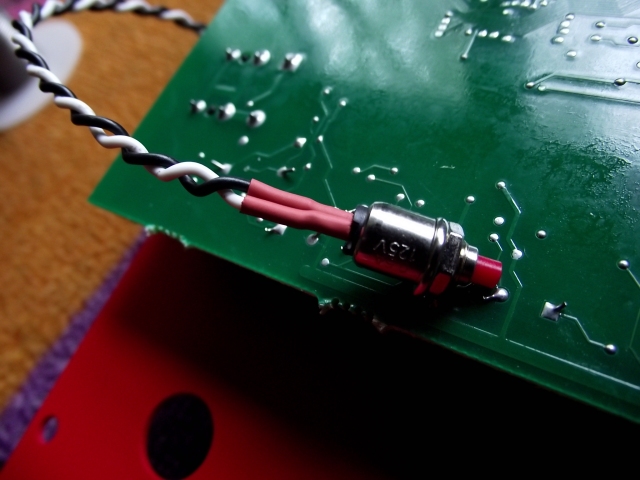


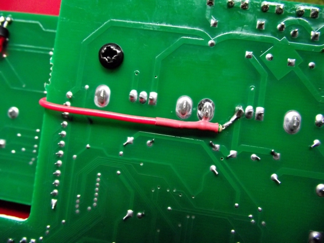



GEAT!!
Nice job man, but I have a doubt… what is need to be done if using a momentary 3PDT switch instead? that is just to avoid drilling the small whole for the small switch
The small switch is needed for calibrating the foot-pedal if you want to make the pedal true-bypass. If you need to replace the original switch then sure, a momentary 3PDT will do the job fine, but it won’t be true-bypass.
Hi there, im not too experienced in electronics do you have any layouts to do this?
Ivan, I do not have a layout at the moment. I’ve been really busy and there’s quite a few things that I have wanted to add the blog but I just don’t have that much time right now. I could however try to come up with something in the next few days.
Cheers,
Ilyich.